Design for Manufacturing / Corners and Radii
DfM Deep Dive
Corners and Radii: Where Plastic Really Breaks
Every geometric disturbance bends the stress lines and drives them up locally. A hole, a sharp inside corner, a sudden thickness jump: all are captured in the stress concentration factor Kt, where the peak stress equals Kt times the nominal stress. Kt is a purely geometric factor; a sharp inside corner without rounding theoretically goes to infinity, and in practice that means: that's where the crack starts.
Plastic is also extra notch-sensitive. Metals with high toughness redistribute a stress peak by locally flowing; plastic does this much worse. Amorphous plastics (PS, SAN, PC in thick sections) are the most notch-sensitive, semi-crystalline materials (PP, PE, PA, POM) tolerate notches better but lose that tolerance at low temperature, and glass-filled materials are stiff but brittle due to their low elongation at break.
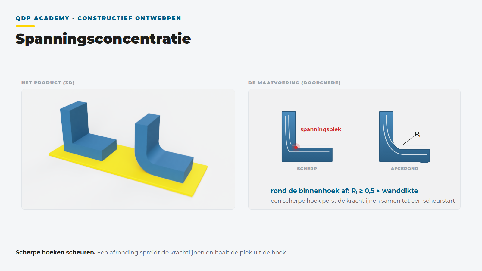
Rounding Radius Versus Wall Thickness
| Ratio r/t | Effect (indicative) |
|---|---|
| < 0,1 | Very high peak, Kt > 3: crack initiation virtually guaranteed under varying or impact loading |
| 0,25 | Kt around 2: still significant, only acceptable in unloaded locations |
| 0,5 | Kt around 1.5: the practical minimum for loaded corners |
| 1.0 and higher | Kt approaches 1.2 to 1.3: further increase yields little extra |
Inside radius at least 0.5× wall thickness, for loaded transitions preferably 0.5 to 1.0×. Outside radius = inside radius plus wall thickness, so the wall thickness remains constant in the corner. Too large a radius causes a material buildup with sink marks and voids: maintaining constant wall thickness through the bend is the criterion.
The Practical Pitfall: Sharper Than Drawn
A lesson you won't find in any handbook: an unspecified radius becomes a sharp corner in the mold. A sharp inside corner in the product is a sharp outside corner on the mold core, and that is the easiest and cheapest version for the mold maker. If there is no explicit radius on the drawing, the product almost always comes out of the mold sharper than the designer intended. It functions during the first tests and then fails months later in the field, exactly at that corner.
That's why at QDP we explicitly dimension every functional radius on the drawing and discuss it in the DfM review with the mold maker. "Radius everywhere 0.5 mm unless otherwise indicated" in the drawing title block is the safety net, not the solution.
View the full DfM pillar or go to wall thickness.
What does this mean for your design?
Calculate your mold and unit price in 2 minutes, or ask our engineers for a DfM check.