Design for Manufacturing / Holes and Cores
DfM Deep Dive
Holes and cores: inexpensive, provided they are well placed
Holes are inexpensive in injection molding: a steel core pin in the mold, no secondary processing. But their position and orientation determine whether that remains true. Too close to the edge or too close to each other, thin material bridges form that fill poorly, are weak, and create vulnerable steel sections in the mold.
Position and Direction
- Distance from hole edge to part edge at least 2× the hole diameter (minimum 1× the wall thickness as an absolute lower bound).
- Distance between two holes at least 2× the largest hole diameter.
- Holes in the ejection direction are free: a core pin in one of the two mold halves.
- Holes perpendicular to the ejection direction require a slider or core puller and make the mold more expensive; for each perpendicular hole, consider whether it can be angled, moved, or made as an open slot.
Through vs. Blind
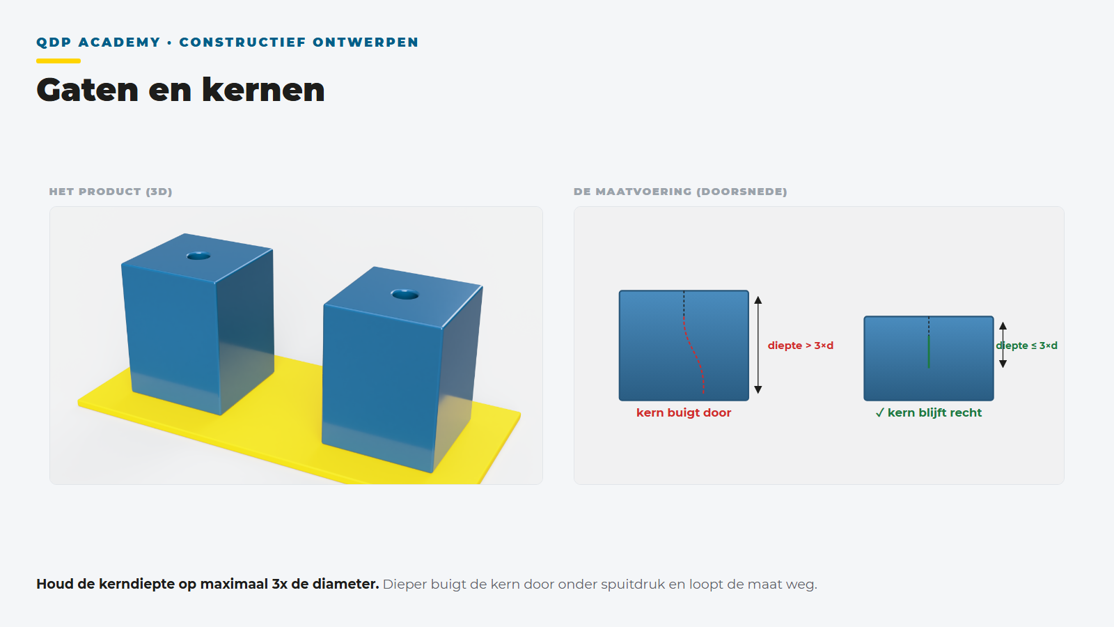
Through holes are preferable: the core pin is supported on both sides or passes through to the other mold half and does not bend. Blind holes are on a core pin clamped on one side; the melt pressure bends this pin, resulting in an off-center or shifted hole.
| Type | Maximum depth (indicative) |
|---|---|
| Blind hole | 3× the diameter (for diameters under 1.5 mm: maximum 2×) |
| Through hole | 4 to 6× the diameter per supported side |
| Bottom thickness under blind hole | minimum 1× the hole diameter |
The weld line behind the hole
The melt splits around each core and rejoins behind it: there is a weld line behind every hole. Therefore, do not place holes in the highest loaded zone or in the center of the main visible surface, or steer the weld line with the gate position to a non-critical location.
See the full DfM pillar or go to weld lines.
What does this mean for your design?
Calculate your mold and unit price in 2 minutes, or ask our engineers for a DfM check.